۵۰۰۰ مدار آمپلی فایر با آی سی

دانلود فایل۵۰۰۰ مدار آمپلی فایر با آی سی

تقویت کننده الکترونیکی وسیله‌ای برای افزایش توان سیگنال می‌باشد. تقویت کننده شکل سیگنال ورودی را حفظ کرده اما دامنه بزرگتر آن را بزرگتر می‌کند.
خب اگر شما هم از آندسته از افرادی باشید که خیلی علاقمند به مدارهای تقویت کننده باشید می دانید که تقویت کننده های ترانزیستور به مراتب توان خیلی بالاتری دارند ولی در همه موارد نمی توان از یک تقویت کننده ترانزیستوری استفاده مرد بلکه استفاده از یک مدارمجتمع تقویت کننده که از ده ها ترانزیستور تشکیل شده بهتر است . پس خب الان که به تقویت کننده های مدار مجتمع علاقمند شدید ما هم براتون ۵۰۰۰ تا مدار اماده کردیم تا با توجه با نیاز خود بهترین مدار را انتخاب کنید .

بالای ۵۰۰ صفحه اطلاعات و شامل ۵ هزار مدار آمپلی فایر با آی سی

مدار موزیک ملودی ساده ۵ ولتی

مداری که برای دوستان گرامی آماده کرده ایم یک مدار موزیک ملودی ساده میباشد که تنها با دو عدد ترانزیستور ساده می تواند یک موزیک برنامه ریزی شده موزیکال دلنشین را پخش کند که راز این مدار در آیسی یا همان ترانزیستور um66 نهفته است و این ترانزیستور در اصل یک آیسی برنامه نویسی شده موزیک است که موزیک خورجی اش به وسیله ترانزیستور منفی رو به رو تقویت می شود .

ساخت آهنگساز ساده الکترونیک با کمترین هزینه

توسط UM66

این قطعه در اکثر شهرستان ها هم پیدا میشه

این هم یک لینک که انواع UM66  را دارد

۱۰ نوع موزیک  مختلف  با این آی سی

تراشه UM66 یک تراشه آهنگساز ساده هست که در اسباب بازی ها، تلفن ها، و … کاربرد دارد. این تراشه بسیار شبیه به ترانزیستور است چرا که سه پایه دارد.تصاویر زیر این تراشه رو نشون میده. اولی شکل واقعی این تراشه و دومی طرز قرار گرفتن پایه هاش رو نشون میده. این تراشه حتی با ۱٫۵ ولت هم کار میکنه. حداکثر ولتاژ هم ۹ ولت هست.

خب حالا باید توضیح بدم. اگر این تراشه رو روبروی خود نگه دارید چنان که طرف تخت آن که مشخصات تراشه روی آن نوشته شده است روبروی شما باشد.اولین پایه از سمت چپ باید به پین منفی باتری یا منبع تغذیه شما وصل گردد و دومین آن به پین مثبت و سومی به بلندگو و پایه دیگر بلندگو را هم به منفی وصل کنید.این برای باتری های ساعت و سایر باتری های کوچک است.

نکته : اگر تراشه داغ کرد، یک مقاومت ۱۰ اهم یا کمتر را با پین منفی یا مثبت تراشه سری کنید.

۱۰ نوع موزیک  مختلف  با این آی سی

————————————————————
آی سی ملودی UM66 – آژیر سه صدا – ۶۹L

آی سی ملودی UM66 – الیزه – ۱۹L

آی سی ملودی UM66 – امام علی(ع) – ALI

آی سی ملودی UM66 – ای ایران – ۱۶L

آی سی ملودی UM66 – ترکی – ۲۶L

آی سی ملودی UM66 – تولدت مبارک – TVM

آی سی ملودی UM66 – زنگ پاناسونیک – PR

آی سی ملودی UM66 – عربی – ۲۵L

آی سی ملودی UM66 – هندی – ۲۸L

آی سی ملودی UM66 – پلیس – ۵۳L


تایمر کلید روشنایی

تایمر کلید روشنایی
How the timer light switch works?

Normally T1 is turned off by P1 and R2. When the trigger switch S1 is pressed the base of T1 is connected to the +12V supply via R2. Now T1 turns on and this action turns on the next transistor T2 which in turn energises the white LED (D2). Resistor R4 limits the operating current of white LED (D2).

When the switch is pressed is current also flows into capacitor C1 (through R1) and charges it. So when the switch S1 is released the charge in the capacitor C1 keeps T1 turned on until the charge has decayed away through R2 and P1. You can easily increase the ouput on time by increasing the resistance of the potentiometer P1.

تایمر تاخیر ۱۲ ولتی


تایمر تاخیر ۱۲ ولتی
۱۲V Time Delay Relay Circuit

Protect your equipments with this tiny 12V time delay relay circuit. The SMPS based power supply of these modern electronic devices is vulnerable to spikes in the mains line so it gives a time delay of one minute before applying power to the device. This prevents deleterious effects due to inrush current and spurious spikes at power on.

Inrush current at power on or power resumes after a power failure can cause unexpected damage in SMPS based power supply of electronic devices. The spurious spike in the power supply when power resumes is due to heavy magnetic flux in the distribution transformer in the mains network. If a short delay is provided, such damages can be avoided. The time delay relay circuit described here is intended for this purpose. It gives power to the device only after one to two minutes of delay after the power is switched on. The circuit is a zener controlled switch.

Capacitor C1 charges through R1 and VR. When the voltage in C1 rises above 3.1 volts, zener conducts to trigger T1. The relay connected to the collector of T1 energizes and power will be available through the common and Normally Open contacts of the relay. Relay remains latched as long as the voltage level in the mains is normal. Capacitor C2 keeps the base bias of T1 steady so that relay clicking can be avoided. Diode D1 prevents back EMF when T1 switches off. Red LED indicates the Relay On status. Delay time depends on the value of C1.

تایمر ۱۰ دقیقه

تایمر ۱۰ دقیقه
The 555 adjustable timer circuit starts timing when switched on. The green LED lights to show that timing is in progress. When the time period is over the green LED turns OFF, the red LED turns ON and the beeper sounds. The time period is set by adjusting the variable resistor. It can be adjusted from 1 to 10 minutes (approximately) with the parts shown in the diagram. You can mark the times on a scale drawn on the box.

Please note that the range of time periods is only approximate. With perfect components the maximum time period should be 4½ minutes, but this is typically extended to about 10 minutes because the 220µF timing capacitor slowly leaks charge. This is a problem with all electrolytic capacitors, but some leak more than others. In addition the actual value of electrolytic capacitors can vary by as much as ±۳۰% of their rated value.

تایمر ساده ۱۲ ولت با آی سی ۵۵۵ از یک ثانیه تا ۱۵ دقیقه

مدار مذکور یک تایمر ساده با آی سی تایمر ۵۵۵ است که دارای دو مد مجزا می باشد. یک مد برای زمان های ۱ تا ۳۰ ثانیه و مد دیگر برای زمان ۱ الی ۱۵ دقیقه. البته زمان با تغییر خازن بزرگ روی برد تا ۳۰ دقیقه و حتی بیشتر نیز قابل افزایش است. مدها را می توان توسط دیپ سوئیچ کوچک روی برد انتخاب کرد و برای تنظیم زمان نیز می توان از ولوم ۱M اهم بهره گرفت. پس از اتصال تغذیه تا زمانی که کلید فشاری فشرده نشود رله همچنان در حالت قطع خواهد بود؛ به محض فشردن کلید فشاری و قطع آن (یک پالس کامل) رله وصل شده و پس از گذشتن زمان تنظیم شده قطع می شود. خروجی رله دارای دو کنتاکت عادی قطع و عادی وصل می باشد که می توان از حالت معکوس نیز برای مصارف خاص بهره برد. بطور مثال دستگاه مورد نظر همیشه در حال کار باشد و با زدن شستی به اندازه زمان تنظیم شده متوقف شود (استراحت دستگاه) و مجدداً شروع بکار نماید. ولتاژ کاری این کیت ۱۲ ولت مستقیم می باشد. این کیت بر اساس نقشه معروف زمانسنج با آی سی مشهور ۵۵۵ طراحی و ساخته شده است که بر اساس زمان پر و خالی شدن خازن کار می کند.

مدار زمان بندی از ۳۰ ثانیه تا ۲۴ ساعت!با ایسی۴۰۶۰


تایمر قوی از ۳۰ ثانیه تا ۲۴ ساعت

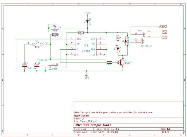
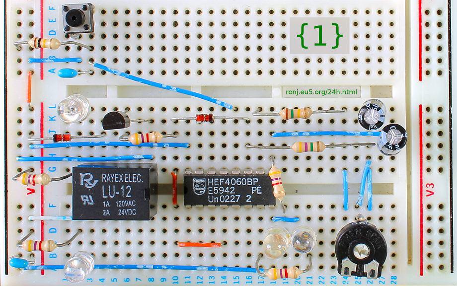
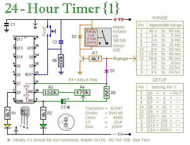
به کمک این مدار جالب و پایه های ایسی CD4060 می توانید مداری درست کنید که از زمان ۳۰ ثانیه تا ۲۴ ساعت، یکی از پایه ها خود را فعال کند ( و در نتیجه رله فعال شود !)

به کمک جدولی که در کنار مدار گذاشته شده.می توانید متناسب به زمان مد نظرتان،پایه ایسی را انتخاب کنید .
پایه ۵ ایسی،زمان ۳۰ تا ۹۰ ثانیه می تواند خروجی به شما تحویل دهد
پایه ۴ ایسی،زمان ۱ تا ۳ دقیقه می تواند خروجی به شما تحویل دهد
پایه ۶ ایسی،زمان ۲ تا ۶ دقیقه می تواند خروجی به شما تحویل دهد
پایه ۱۴ ایسی،زمان ۴ تا ۱۲ دقیقه می تواند خروجی به شما تحویل دهد
پایه ۱۳ ایسی،زمان ۸ تا ۲۰ دقیقه می تواند خروجی به شما تحویل دهد
پایه ۱۵ ایسی،زمان ۱۵ تا ۴۵ دقیقه می تواند خروجی به شما تحویل دهد
پایه ۱ ایسی،زمان ۶ تا ۲ ساعت می تواند خروجی به شما تحویل دهد
پایه ۲ ایسی،زمان ۱۲ تا ۴ ساعت می تواند خروجی به شما تحویل دهد
پایه ۳ ایسی،زمان ۸ تا ۲۴ ساعت می تواند خروجی به شما تحویل دهد
برای تنظیم زمان های هر پایه باید از مقاومت متغییر R4 استفاده کرد.


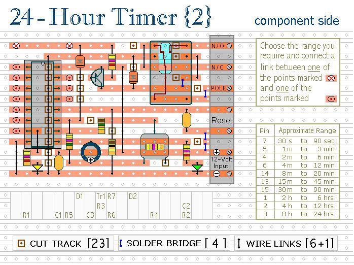
دانلود فایل پی سی بی
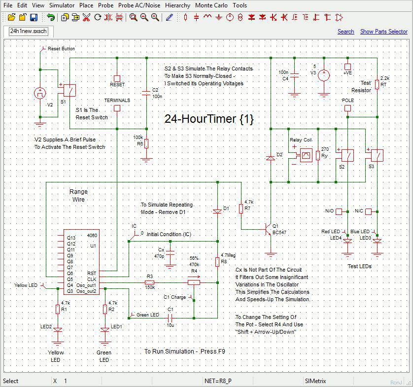
 

دانلود شماتیک


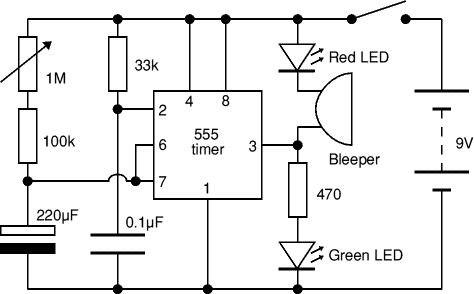
Timer Circuits With 4060B

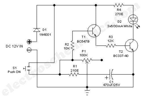
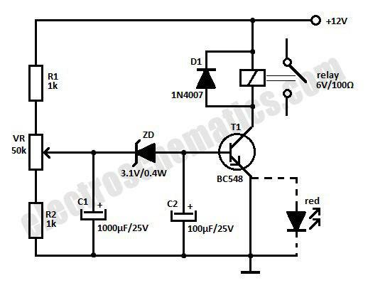
These two circuits are multi-range timers offering periods of up to 24 hours and beyond. They can be used as repeating timers – or as single-shot timers. Both circuits are essentially the same. The main difference between them is their behaviour in single-shot mode.

In single-shot mode – when the preset time has elapsed – Version 1 energizes the relay and Version 2 de-energizes the relay. The first uses less power while the timer is running – and the second uses less power after the timer has stopped. Pick the one that best suits your application.

The pins of the 4060B integrated circuit output the running count in binary as shown below:

۰ = ۰۰۰۰۰۰۰۰۰۰
۱ = ۰۰۰۰۰۰۰۰۰۱
۲ = ۰۰۰۰۰۰۰۰۱۰
۳ = ۰۰۰۰۰۰۰۰۱۱
۴ = ۰۰۰۰۰۰۰۱۰۰
۵ = ۰۰۰۰۰۰۰۱۰۱
۶ = ۰۰۰۰۰۰۰۱۱۰
۷ = ۰۰۰۰۰۰۰۱۱۱
۸ = ۰۰۰۰۰۰۱۰۰۰

Notes

The Cmos 4060 is a 14-bit binary counter. However – only ten of those bits are connected to output pins. The remaining bits – Q1, Q2, Q3 and Q11 – do exist. You just can’t reach them.

The 4060 also has two inverters – connected in series across pins 11, 10 & 9. Together with R3, R4, R5 and C3 – they form a simple oscillator.

While the oscillator is running – the 14-bit counter counts the number of oscillations – and the state of the count is reflected in the output pins.

By adjusting R4 you can alter the frequency of the oscillator. So you can control the speed at which the count progresses. In other words – you can decide how long it will take for any given output pin to go high.

When that pin goes high – it switches the transistor – and the transistor in turn operates the relay.

In single-shot mode – the output pin does a second job. It uses D1 to disable the oscillator – so the count stops with the output pin high. .

If you want to use the timer in repeating mode – simply leave out D1. The count will carry on indefinitely. And the output pin will continue to switch the transistor on and off – at the same regular time intervals.